Optimize important parameters for DC Fan operation
- Home>>News>>Company NewsOptimize important parameters for DC Fan operation
Optimize important parameters for dc fan operation
Dc fans are a major component of any engineer's thermal management solution, designed to dissipate heat for applications through efficient forced air cooling. Although DC fans are well known and easily recognizable components, a basic understanding of airflow and other key parameters is required to ensure that the fan selected is best suited to the needs of the system. To help understand these parameters, this article discusses how to correctly calculate airflow and wind pressure, adjust these parameters to fit the fan's operating curve, and the effects of a multi-fan design.
Overview of flow parameters
It is important to understand the various airflow and heat transfer parameters before specifying fans. Forced flow works by absorbing heat from an object and then transferring it elsewhere to dissipate, with the energy transferred depending on the mass, specific heat and temperature variation of the forced flow.

The mass of the forced flow is calculated from the volume and density of the flowing air.

If the second formula is inserted into the first one, the dissipated energy can be related to the wind volume.

Next, divide both sides by time to produce the following formula.

Usually, the excess power is known and the flow (volume/time) is unknown, which means that the formula can be reformulated as:

The formula is usually written as:

Among them
Q = airflow
Q = Heat to dissipate
ρ = air density
Cp = specific heat of air
δ T = The temperature at which the air will rise as it absorbs heat to dissipate
K = a constant, depending on the units used in the other parameters
At sea level, the density of dry air at 68°F (20°C) is 0.075 LBS /ft3 (1.20 kg/m3), while the specific heat of dry air is 0.24 Btu/lb °F (1 kJ/kg °C). Inserting these values simplifies the above formula as:

Among them
Qf = flow, in cubic feet per minute (CFM)
Qm = flow, in cubic meters per minute (CFM)
Q = Heat to dissipate, in watts
δ TF = The temperature, in °F, at which air will rise as it absorbs heat to dissipate
δ TC = The temperature at which the air will rise as it absorbs heat to dissipate, in units of °C
Air pressure requirements
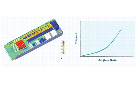
Although the above formula addresses the airflow rate required for adequate cooling, the wind pressure generated by the fan needs to be calculated. The airflow path through the system creates airflow resistance, which means that the fan must be able to generate enough wind pressure to force the specified volume of air through the system to achieve the desired cooling effect. However, each system generates unique wind pressure requirements and therefore cannot be reduced to a formula like airflow rate. Fortunately, many CAD products can be used to model wind pressure and airflow characteristics at the design stage. Once the design is complete, these characteristics can be further measured using anemometers and manometers.
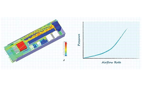
Figure 1: Modeling of airflow and wind pressure
Generate airflow and wind pressure requirements
As described in the previous section, a fan (or fans) needs to produce a certain airflow rate and pressure to achieve the desired cooling effect. The manufacturer's specification will provide the following information: airflow rate without backpressure, maximum wind pressure without airflow rate, and airflow to wind pressure performance curve of the fan.
In this example, based on the heat and air temperature constraints to be eliminated, a flow rate of 10 CFM or higher is calculated for the product, and the mechanical design of the product produces a flow with respect to the wind pressure diagram shown below (Figure 2). The dotted line shows the minimum airflow required, while the orange curve shows the relationship between airflow and wind pressure.
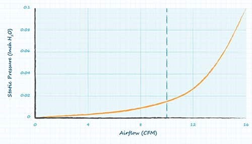
Figure 2: Minimum flow plotted on airflow-wind pressure curve
Using the figure above, we selected CUI Devices' CFM-6025V-131-167 DC axial fan, whose specifications specify a no-back flow rate of 16 CFM and a no-flow static pressure of 0.1 inH2O, and provide the following performance diagram (Figure 3).
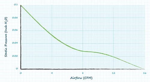
Figure 3: CfM-6025V-131-167 performance curve of CUI Devices
Figure 3 can then be superimposed on Figure 2 to produce the graph shown in Figure 4, which highlights the operating point of the selected fan. It is important to note that although the operating point of 11.5 CFM in this example exceeds the airflow requirement of 10 CFM, some applications will require a greater thermal operating margin. Therefore, you need to choose fans with different performance specifications.
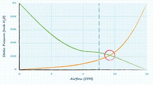
Figure 4: Fan operating points indicated by red circles
Multi-fan design and operation
Larger or faster fans generally provide greater maximum airflow and wind pressure. However, when a single fan cannot meet the task requirements, you can improve some performance parameters by connecting multiple fans in parallel or in series. For example, fans operating in parallel will increase the maximum airflow but not the maximum wind pressure, while fans operating in series will increase the maximum wind pressure but not the maximum airflow.
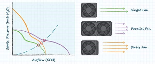
Figure 5: Single fan, parallel fan and series fan operation.
The flow-pressure performance curves of parallel or series fans are the same as those of a single fan, except that the airflow or pressure values are multiplied by the number of fans operating in parallel or series, respectively. The following example (Figure 6) shows this situation, where the airflow value is multiplied by the number of fans in parallel.
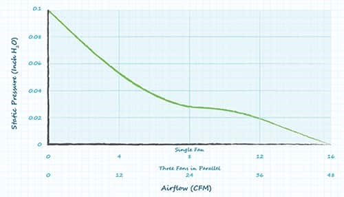
Figure 6: Airflow multiplied by the number of parallel fans, or wind pressure multiplied by the number of series fans.
In general, the shunt fan design is well suited for high wind pressure and low wind pressure applications, while the series fan design is better suited for high wind pressure and low wind pressure applications.
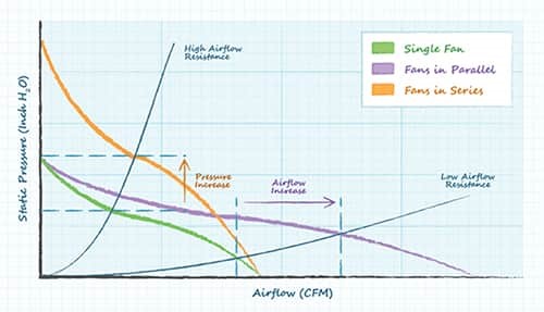
Figure 7: Comparison of fan performance under high and low airflow resistance
Fan speed and fan similarity law
The fan speed (RPM) affects the air volume, air pressure, power consumption, and noise generated by fans. These relationships are further summarized by the "fan similarity Law" :
• The amount of air that the fan moves is proportional to the fan speed.
O CFM alpha RPM
Example: 4 x RPM Generates 4 x CFM
• The wind pressure generated by the fan is proportional to the square of the fan speed.
O Wind pressure α RPM2
Example: 2 x RPM Generates 4 x air pressure
• The power required for fan operation is increased by cubic fan speed.
O Power alpha RPM3
Example: 4 x RPM Requires 64 x power
• When the fan speed is doubled, the noise generated by the fan increases by 15 dB.
O Example: In general, an increase of 10 dB in noise will double the level of noise perceived by the human ear.
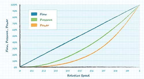
Figure 8: Fan similarity law
Conclusion
A basic understanding of the airflow and pressure requirements outlined in this article can assist the designer in selecting the right fan to meet the forced air cooling requirements of their application. When a single fan cannot meet the calculated air flow or pressure parameters, connecting fans in parallel or in series provides engineers with more options.
- Max air flow fans
- Machine cooling fan
- Bitcoin digger fan
- Telecome fan
- Stage lamp fan
- Power cooling fan
- Laser module fan
- Min air flow fans
- 3D printer fan
- Amplifier fan
- Computer fan
- Inverter fan
- Charging pile fan
- Car LED lamp fan
Contact
Black@ruiapple.com
TEL:+86 13189756968
FAX:+86 755 88852020
Shenzhen Office: 508#,Tianhe biulding, Baoan Road,Shenzhen,China Factory add: 471#, West Wenwu Road, Economic and Technological Zone, Mianyang City, Sichuan Province, China
Copyright © 2019 SHENZHEN RUIAPPLE ELECTRONICS CO.,LTD Official Record No:蜀ICP备2024086499号-2
Support:RUIAPPLE


