Fan Types - Why choose an Axial fan
- Home>>News>>Company NewsFan Types - Why choose an Axial fan
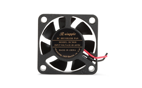 |
When we have defined the volume flow rate that we require, whether this is to provide fresh air or process cooling, we need to combine this with the resistance to flow that the fan will encounter in the application. The volume flow rate, (in m3/hr) and the pressure (in Pascals - Pa), are combined to become the duty point against which the fan must operate. It is important that we select a fan whose performance characteristic meets the required duty point on or near the point of peak efficiency. Using the fan at its peak efficiency minimises the power consumption and noise emitted from the fan whilst delivering the required performance.
How does an axial fan work?
An axial fan blade works on the same principle as how an aircraft wing generates lift. The wing of an aircraft has an aerofoil shape which as it is propelled forwards the air is diverted above and below the wing. The air above the wing has farther to travel than the air under the wing which results in a difference in air velocity above and below the wing. The higher velocity air stream above the wing has a higher dynamic force which results in a lower static pressure. Below the wing, the air is moving slower which means it has a lower dynamic force and higher static pressure. The difference in higher pressure below the wing and lower pressure above it generates lift.
Aircraft Fan
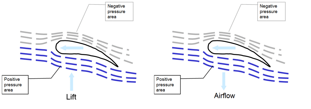
In the case of a fan we use an impeller blade like an aerofoil however instead of generating lift we keep the fan blades rotating in a stable axis and this creates airflow. This follows Newton’s third law of motion that for each action there is an equal and opposite reaction. The air above the aerofoil is drawn into the fan by the reduction in static pressure and pushed out through the fan creating a positive pressure area.
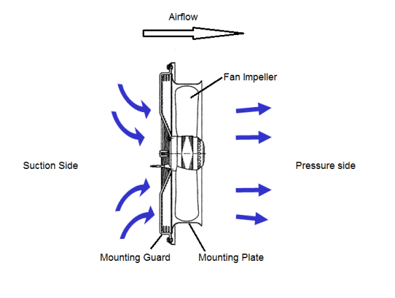
To direct the airflow and obtain optimum performance, we use a mounting plate with a bell-mouth shaped inlet cone to create a smooth laminar flow into the suction side of the fan. The fan is held centrally in the mounting plate by the mounting guard which maintains a small tip clearance between the fan and bell-mouth.
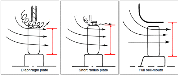
There are other methods of mounting an axial fan including placing it in a plain diaphragm hole or in a short radius, however, these mounting methods compromise performance. Using a full bell-mouth mounting plate will ensure that optimum performance from the fan will be achieved.
Reduction in the effective diameter using alternative mounting methods
Fan characteristic
The optimum operating area on an axial fan characteristic is below what is called the stall dip. An axial fan works best when a relatively high-volume flow is required against a relatively low system pressure. The graph below illustrates the optimum working area…
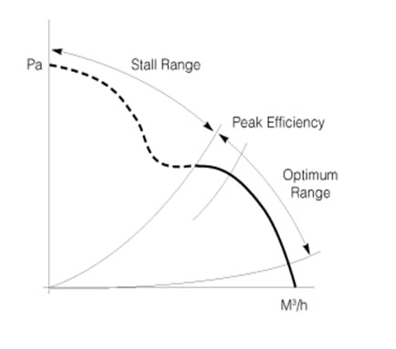
The volume flow is plotted along the X-axis and the system pressure is plotted on the Y-axis. When there is no pressure in the system, (the fan is blowing freely), an axial fan will produce the greatest volume flow. As a resistance to flow is applied to the suction or exhaust side of the fan the volume flow rate will drop. The peak efficiency is at a point called the knee of the fan characteristic curve. At this point, the ratio of the output power of the fan (Volume flow x Pressure development) and the electrical power input is at its greatest and the sound pressure being produced by the fan will be at its quietest.
Above the optimum range of operation, the flow across the upper and lower sides of the impeller blades becomes turbulent and the impeller starts to go into an aerodynamic stall.
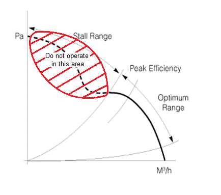
At this point, the fan will start to vibrate and create lots of noise. Operating at this point can potentially cause the motor driving the fan to overheat as the turbulent forces on the impeller blade disrupt the motor operating efficiency.
Mounting considerations – clearances
When installing an axial fan, it is important to consider several factors relating to how it is mounted to the application. Ideally, when we choose an axial fan we could allow for lots of room on both the suction side and exhaust side of the fan to promote an even airflow into the fan and a controlled dispersal of the air on the exhaust side of the fan. Unfortunately, this may not always be possible to achieve and a compromise must be reached.
As a rule of thumb, the clearance (x) on the suction side and the exhaust side of the fan before an obstruction is reached should be at least 1/3rd of the diameter of the fan.
X >= diameter D x 0.33
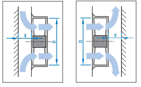
e.g. For an axial fan of 450mm diameter, there should be at least 150mm of clearance between the fan and an obstruction to flow (Coil, Filter, wall etc…)
- Max air flow fans
- Machine cooling fan
- Bitcoin digger fan
- Telecome fan
- Stage lamp fan
- Power cooling fan
- Laser module fan
- Min air flow fans
- 3D printer fan
- Amplifier fan
- Computer fan
- Inverter fan
- Charging pile fan
- Car LED lamp fan
Contact
Black@ruiapple.com
TEL:+86 13189756968
FAX:+86 755 88852020
Shenzhen Office: 508#,Tianhe biulding, Baoan Road,Shenzhen,China Factory add: 471#, West Wenwu Road, Economic and Technological Zone, Mianyang City, Sichuan Province, China
Copyright © 2019 SHENZHEN RUIAPPLE ELECTRONICS CO.,LTD Official Record No:粤ICP备19010273号
Support:RUIAPPLE


